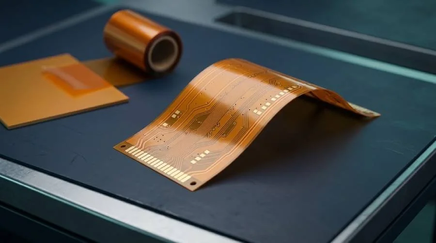
Why polyimide is used in flexible circuits
Polyimide film provides an insulating base for flexible circuitry. In a rigid-flex construction, polyimide-based layers connect rigid sections and allow the circuit to fit a three-dimensional assembly. The complete construction determines whether the design is suitable for the intended installation or motion.
Define the whole material system
A polyimide circuit includes more than the base film. Copper, adhesive or adhesiveless construction, coverlay, bonding materials and local reinforcement all influence thickness, assembly fit and bending behavior.
| Element | What to define |
|---|---|
| Polyimide base | Grade or material requirement and dielectric thickness. |
| Copper | Thickness, copper type and relevant flex requirements. |
| Adhesive and bonding | Construction and permitted material alternatives. |
| Coverlay | Material, openings and local geometry. |
| Stiffeners | Material, thickness, location and attachment requirements. |
Static installation and repeated bending
A circuit folded during installation has different requirements from one that moves repeatedly during service. Identify the bend area, direction, radius and intended motion. Do not assume a flexible base film makes every multilayer construction suitable for dynamic flexing.
Polyimide versus FR-4
FR-4 normally provides the rigid structure of a conventional board, while thin polyimide film enables flexible interconnection. A rigid-flex board can use both within one construction. Material choice must be coordinated with the mechanical drawing, local thicknesses and assembly clearances.
Send the installed configuration
Provide a flat fabrication drawing together with a drawing of the installed shape when available. Mark flexible regions, rigid transitions, stiffeners and connector areas. These details help prevent a correctly fabricated flat circuit from conflicting with the intended enclosure.
Questions, answered
Before your next build
Does polyimide alone define a flex stackup?
No. Copper, bonding layers, coverlay and reinforcement form part of the construction. Define these together with the bend requirements.